Secure Boot verification on TriCore
As a security researcher in the automotive industry, I needed to validate the secure boot feature of the target ECU. The main MCU of the target ECU is based on TriCore architecture, developed by Infineon. In this blog post, I’ll explain how I successfully validated the secure boot features of the target ECU.
Secure Boot is a security technique designed to detect tampering with the code intended to be loaded during the boot process, preventing the execution of tampered code.
Before we dive into the intricacies of secure boot, let’s take a look at the MCU of the target
TriCore is a 32-bit microcontroller architecture widely used in the automotive environment, featuring three cores—RISC, DSP, and MCU. It is referred to as ‘TriCore’ because these three elements are integrated into a single architecture.
The target MCU is TC27x series, and the manual can be referenced at here.
PMU
TriCore manages flash memory and BootROM in program memory units (PMUs). The following figure shows the address map for PMU0.

The BootROM contains the initial code that is executed during the power-up cycle when power is on, called SSW (Startup Software).
Flash memory is divided into PFlash (Program Flash) and DFlash (Data Flash). The PFlash section holds the code for the bootloader and application codes while the DFlash section contains the user data.
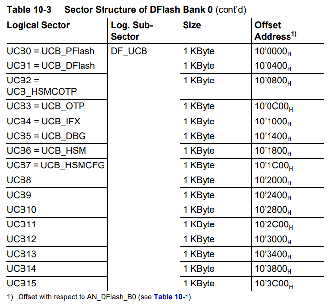
The User Configuration Block (UCB) is also situated in the DFlash area. The UCB is a specific logical sector containing protection settings and other user-configured data.
HSM code and data are also stored within both the PFlash and DFlash.
We’ll cover HSM a little later.
Boot Process
When power is initially supplied, SSW performs system reset, clock configuration, memory initialization. After that, boot mode is selected.
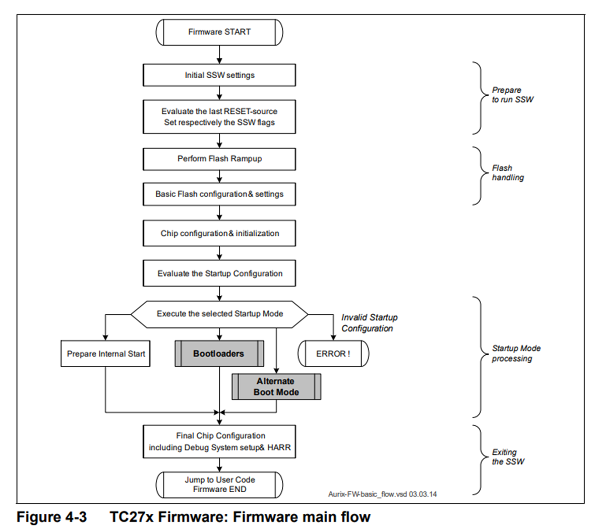
The initial boot mode is the internal flash mode, and in this mode, the bootloader is located at the address 0xA0000020 in the PFlash region.
Additionally, TriCore supports booting using an external bootloader. In the case of TC27x, there are four boot-related configuration headers known as Boot Mode Headers. The Boot Mode Index (BMI) in these headers is used to configure the boot mode.
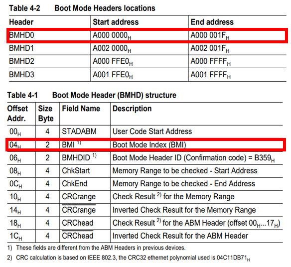
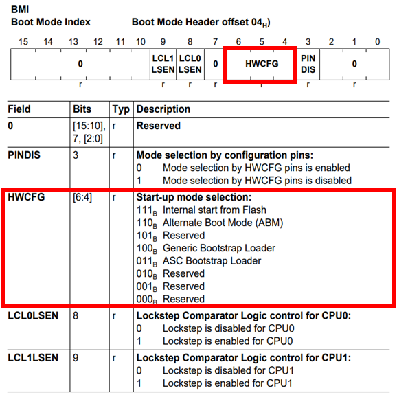
BMI is a 2-byte value, and the HWCFG bit field in BMI influences the startup mode selection. HWCFG is also mapped to actual pins on the chip.
When HWCFG value is 0b111, the system boots from internal flash. Depending on the HWCFG value, booting through an external bootloader is possible. TC27x also supports booting via ASC or CAN protocols.
HSM
After selecting the boot mode, the next steps depend on whether the HSM (Hardware Security Module) feature is enabled or disabled.
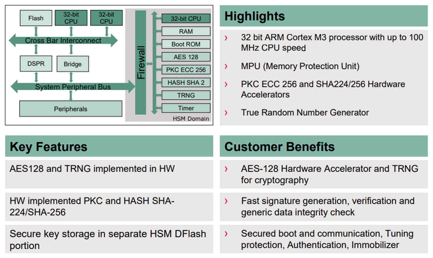
HSM is a hardware security module designed to handle sensitive information or execute sensitive code in a separate on-chip hardware module. It processes tasks such as TRNG (True Random Generator) and encryption internally, and the encryption keys used are stored in the HSM dedicated memory in DFlash.
In TC27x, HSM uses ARM Cortex-M3 processor which is different from the host architecture
The code for HSM is stored in the PFlash in sectors PS0, S6, S16..S17, with memory addresses ranging from 0xA0018000 to 0xA001BFFF and 0xA0060000 to 0xA007FFFF
The data of HSM is stored in DFlash at the address range 0xAF000000 to 0xAF010000.
To safeguard both the data and code of HSM from host access, a feature known as HSM lock is implemented. When engaged, the HSM lock restricts reading and writing access to the HSM region in both PFlash and DFlash.
The HSM lock configuration is set in the UCB (User Configuration Block) area. We will explore this further shortly.
Secure Boot
After selecting the boot mode, the system checks if HSM can be utilized. If HSM is available, it calculates the MAC value for the bootloader to be executed. The calculated MAC value is then compared with the MAC value stored internally in HSM. If these two values differ, the system cannot boot, preventing unauthorized bootloader execution.
In this situation, recovery is not possible, and the controller enters a bricked state. When connecting to the CPU using a JTAG debugger like Trace32, since the debugger attaches from the beginning of the bootloader, if the bootloader is not reached, the debugger cannot be attached.
Therefore, if there is a need to update the bootloader code when secure boot is enabled, it is necessary to either disable secure boot before making changes or update both the code in HSM and the bootloader simultaneously.
If the controller is in a factory reset state, the MAC value for the bootloader is not present in HSM. In this case, the initially calculated MAC value for the bootloader is stored in HSM.
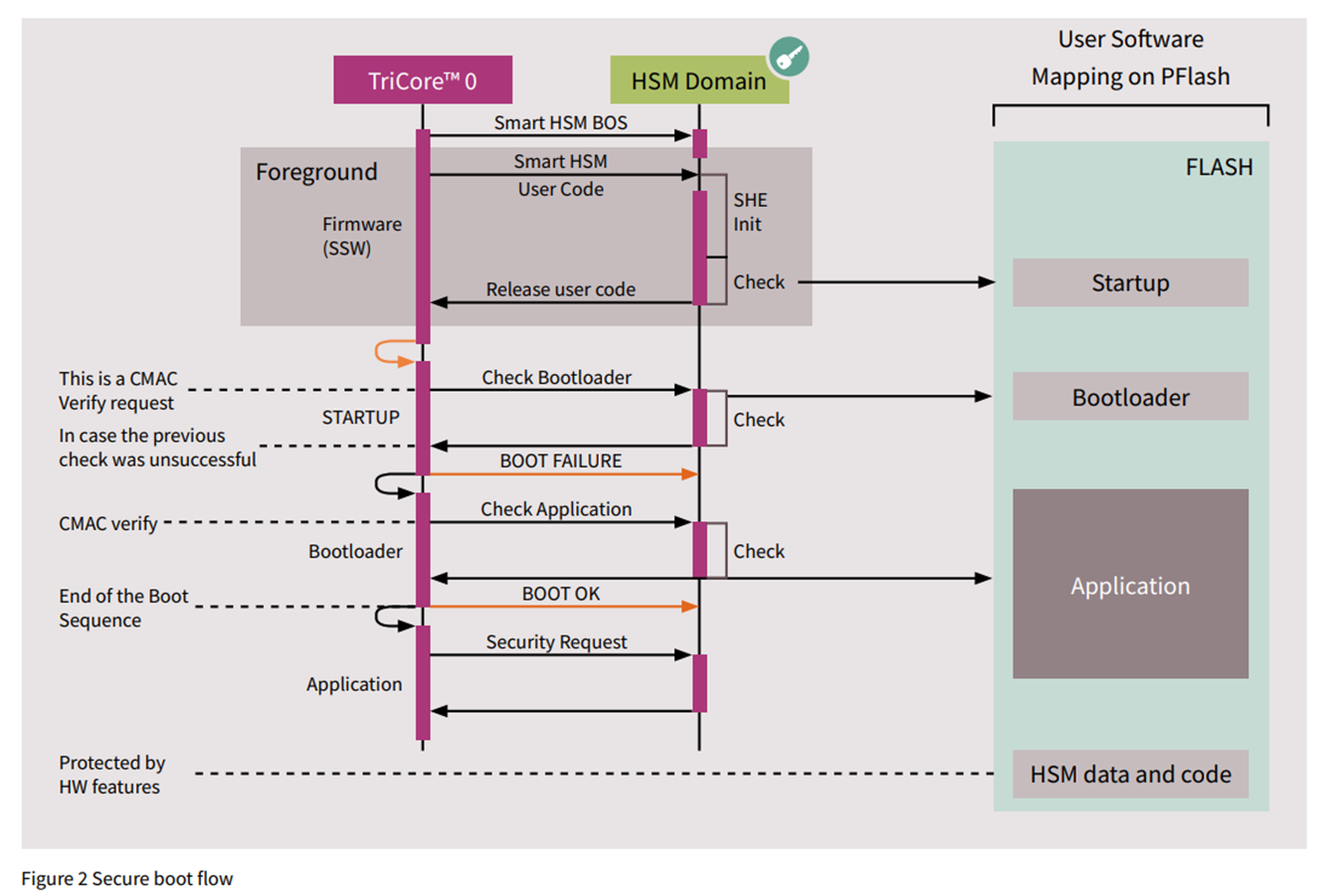
If the newly calculated MAC and the MAC value already stored in HSM memory are identical, the CPU proceeds to jump to the bootloader, and the associated code is executed. Similarly, before transitioning from the bootloader to the main application code, the MAC value for the application area is computed within HSM. Execution of the application code only occurs if the calculated MAC matches the stored MAC value in HSM for the application.
Secure boot operates in this manner, enforcing a verification step where the calculated MAC values must match the stored MAC values before permitting the execution of both the bootloader and subsequent application code.
Therefore, summarizing the secure boot process:
- SSW (Start-Up Software)
- Initialization process and boot mode selection
- HSM (Hardware Security Module)
- Before executing the bootloader, HSM compares the MAC stored in HSM for the bootloader with the newly calculated MAC for the bootloader.
- Execution of Bootloader Code
- HSM (Hardware Security Module)
- Before executing the application code, HSM compares the MAC stored in HSM for the application code with the newly calculated MAC for the application code.
- Execution of Application Code
This is the sequence of events in the secure boot process in TriCore environment.
UCB
To enable secure boot on the system, various security settings must be configured, such as HSM enable, HSM lock, boot mode lock, and secure debug enable. These security configurations are set in the User Configuration Block (UCB) region of DFlash, managed by the PMU (Program Memory Unit)
As HSM has a separate core with its own code, it requires its own booting process. The HSM enable setting determines whether HSM booting is activated. If HSM is in the enabled state, the SSW initiates the booting of HSM’s code.
Additionally, HSM lock is a configuration that prevents host access to data or code in HSM.
Both HSM enable and HSM lock settings can be configured in UCB_HSMCOTP.
Generally, each UCB block consists of registers and confirmation bytes corresponding to that UCB block.
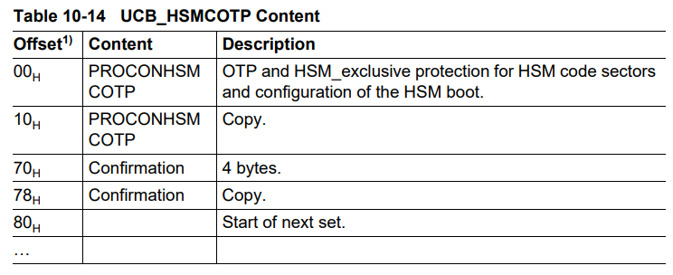
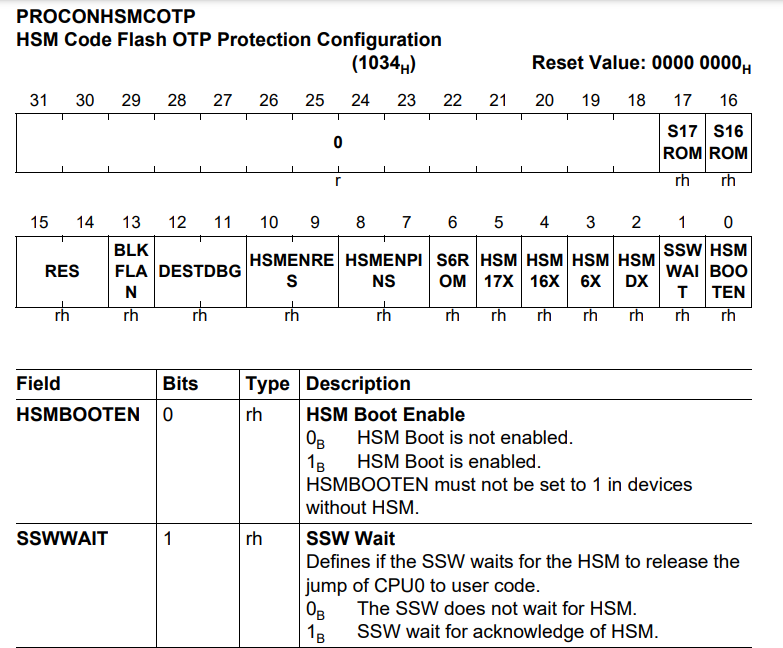
At offset 0x00 of UCB_HSMCOTP, the PROCONHSMCOTP register is located.
Activating HSM booting occurs when the HSMBOOTEN and SSWWAIT bits in the PROCONHSMCOTP register are set to 1. In this state, the CPU waits for a response from the HSM within the SSW.
Also, a copy of the PROCONHSMCOTP register at offset 0x10 of UCB_HSMCOTP must be configured in the same manner.
Additionally, when the confirmation bytes are set to a fixed value of 0x57b5327f, the UCB block is activated. When the UCB_HSMCOTP block is activated, it enters an HSM lock state, where access to data and code in the HSM area from the host core becomes restricted.
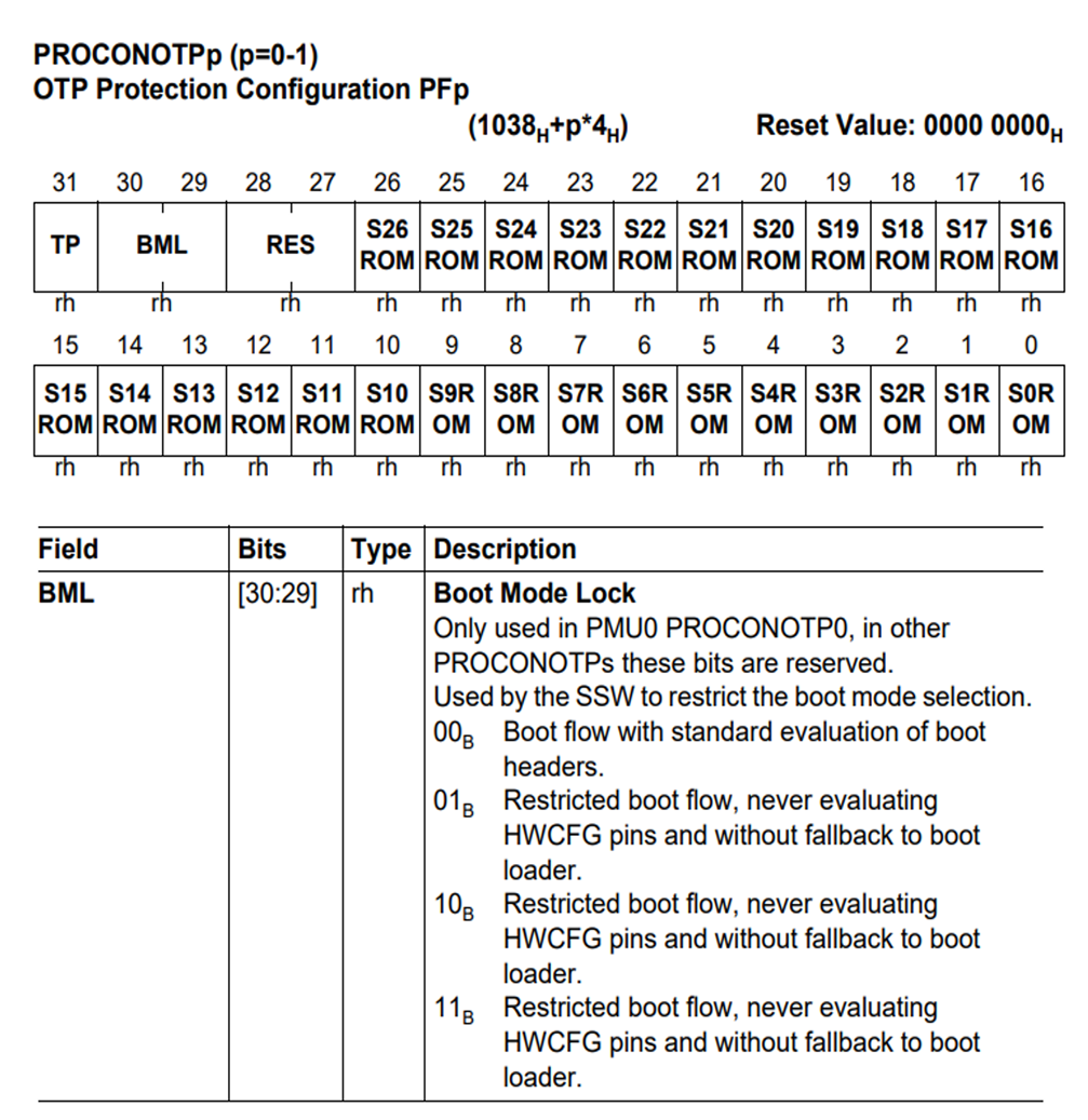
In the UCB_OTP block, you can configure boot mode lock settings.
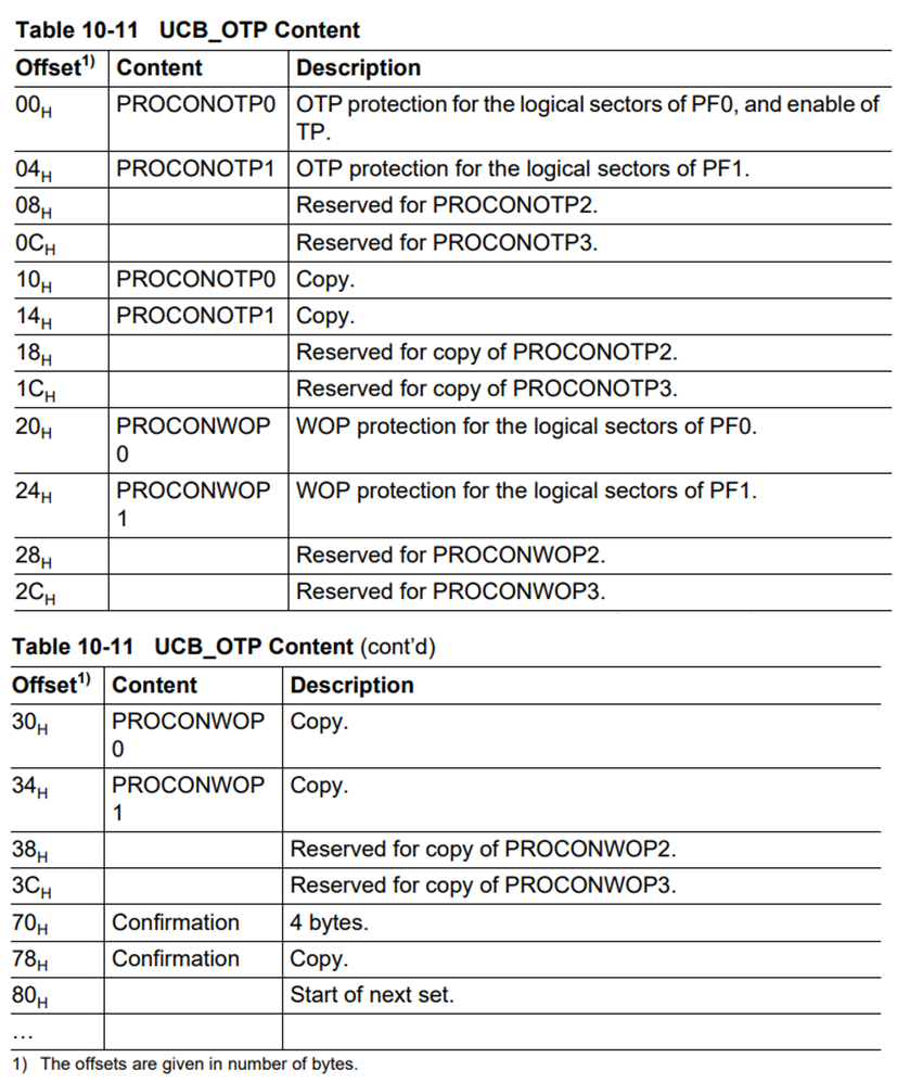
When you set the BML (Boot Mode Lock) field in the PROCONOTP0 and PROCONOTP1 registers to 0b11, you prevent bootloader configuration through the HWCFG pins, forcing booting through internal flash.
After configuring the BML field in the registers, similar to the UCB_HSMCOTP block settings, you need to confirm the settings of the UCB_OTP block by setting the confirmation byte to the value 0x57b5327f.
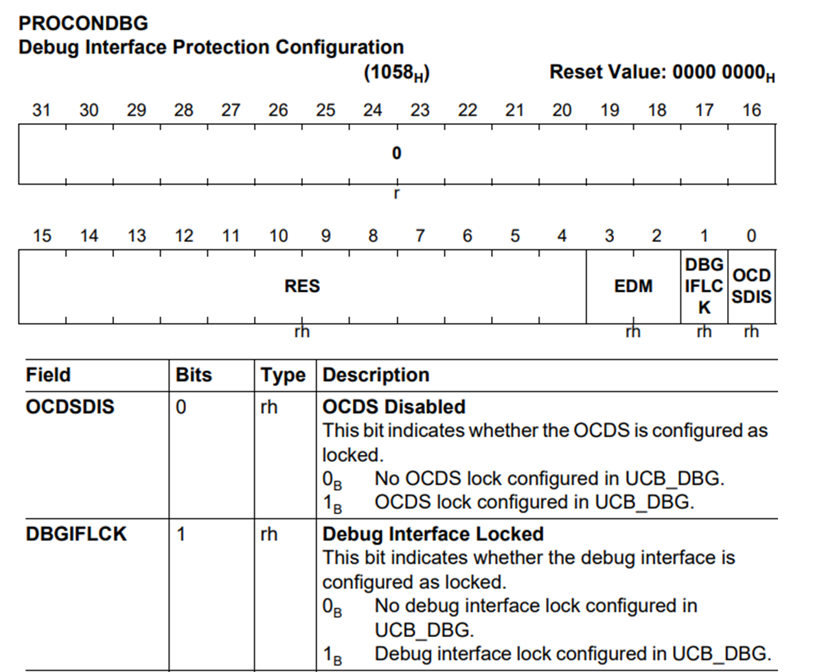
To activate secure boot, the last step involves configuring the UCB_DBG block. Using the PROCONDBG register in the UCB_DBG block, you can set up secure debug, a protection setting for the debug interface.
Basically, many embedded systems, including TriCore, implement access control mechanisms such as password, key authentication, and certificate-based authentication to control access to debug interfaces such as JTAG.
In the case of TriCore, access to the debug interface is protected using a password-based authentication mechanism, ensuring only authorized users can access the system for debugging purposes.
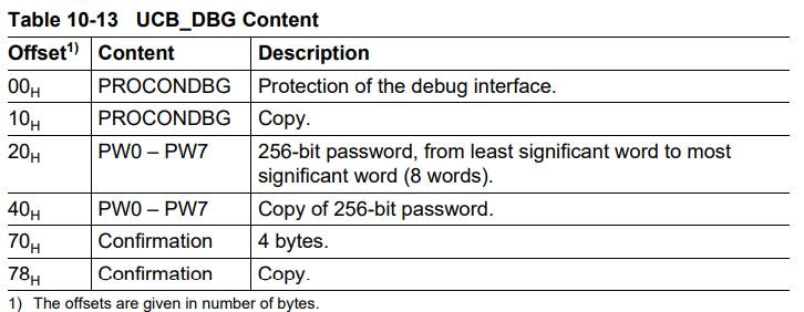
To enable secure debug, the OCDSDID bit and the DBGIFLCK bit in the PROCONDBG register must both be set to 1. Like other UCB blocks, the UCB_DBG block also requires setting the confirmation bytes.
Additionally, a 32-byte password must be set at offset 0x20 of the UCB_DBG block. Once these steps are complete, a debugger can be attached even when secure debug is enabled, provided the correct password is used.
The following table summarizes the UCB settings
| UCB Block | UCB Block Address Range | Related Register | Register Address | Security Method |
|---|---|---|---|---|
| UCB_HSMCOTP | 0xAF100800 – 0xAF100BFF | PROCONHSMCOTP | 0xF8002034 | HSM Enable |
| UCB_OTP | 0xAF100C00 – 0xAF100FFF | PROCONOTP | 0xF8002038, 0xF800203C | Boot Mode Lock |
| UCB_DBG | 0xAF101400 – 0xAF1017FF | PROCONDBG | 0xF8002058 | Secure Debug |
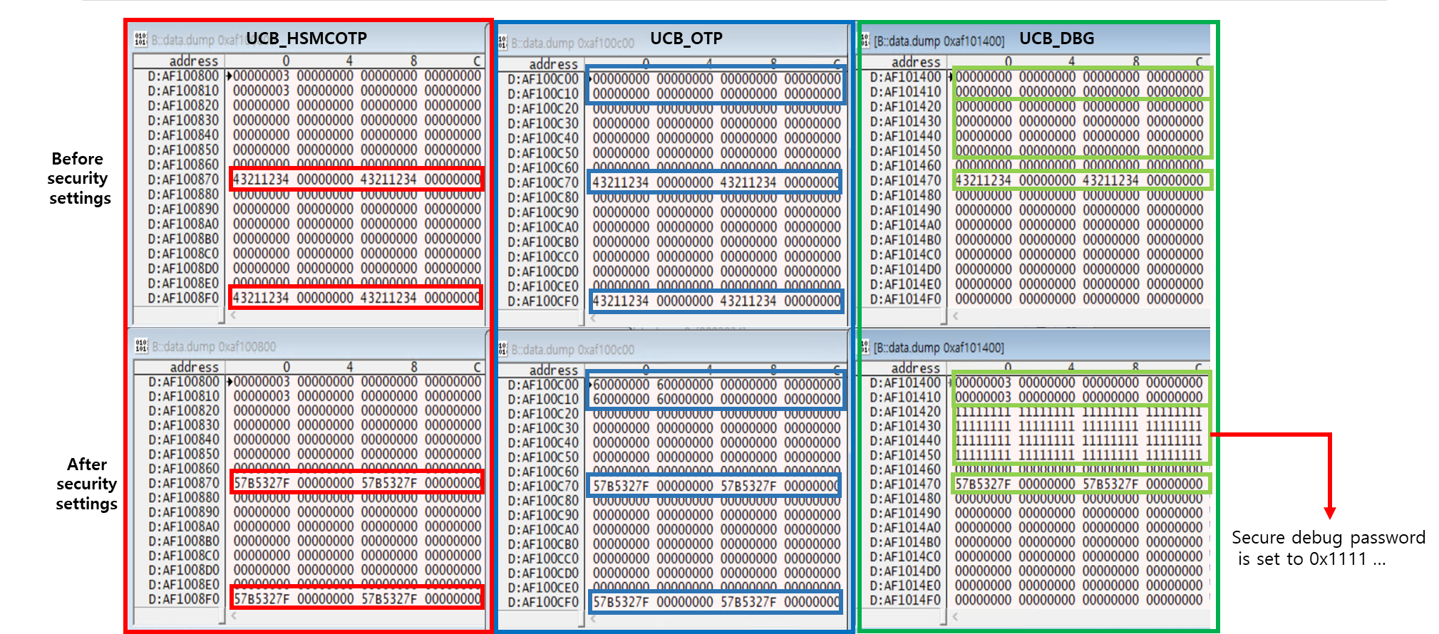
The figure below shows the security features before and after setting them through UCB. The password value for secure debug was set to 32 bytes of 0x11111111…
Since UCB is a DFlash region, I programmed the UCB DFlash region using Trace32. Below is the Trace32 CMM script for programming the UCB region of DFlash.
I dumped the initial data of each UCB region that needed to be modified, then modified the dumped content and overwritten it to the flash memory.
FLASH.RESET
FLASH.Create 1. 0xAF100800--0xAF100BFF 0x400 TARGET Long ; UCB_HSMCOTP
FLASH.Create 3. 0xAF100C00--0xAF100FFF 0x400 TARGET Long ; UCB_OTP
FLASH.Create 2. 0xAF101400--0xAF1017FF 0x400 TARGET Long ; UCB_DBG

FLASH.TARGET 0xC0000000 0xD0000000 0x4000 ~~/demo/tricore/flash/long/tc2.bin

FLASH.ReProgram 0xAF100800--0xAF100BFF /erase
FLASH.ReProgram 0xAF100C00--0xAF100FFF /erase
FLASH.ReProgram 0xAF101400--0xAF1017FF /erase

DATA.LOAD.Binary "C:\ucb_hsmcotp_modified.bin" 0xAF100800--0xAF100BFF
DATA.LOAD.Binary "C:\ucb_otp_modified.bin" 0xAF100C00--0xAF100FFF
DATA.LOAD.Binary "C:\ucb_dbg_modified.bin" 0xAF101400--0xAF1017FF

FLASH.ReProgram off
ECHO "Modified UCB_HSMCOTP successfully installed!!"
ECHO "Modified UCB_OTP successfully installed!!"
ECHO "Modified UCB_DBG successfully installed!!"

ECHO "HSM Enabled"
ECHO "Secure Debug Enabled"
ECHO "HSM Locked"
ECHO "Secure Boot Enabled"
Verification of Secure Boot
If secure boot is enabled, you can connect a JTAG debugger to modify the bootloader code. After resetting the system, you can verify whether the modified bootloader code is executed after the power-up cycle.
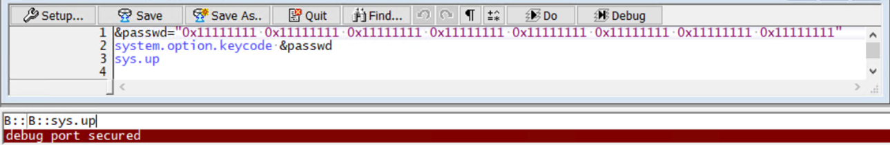
I connected Trace32 to the debug interface using the following commands.
&pw="0x11111111 0x11111111 0x11111111 0x11111111 0x11111111 0x11111111 0x11111111 0x11111111"
SYSTEM.OPTION.KEYCODE &pw
SYSTEM.UP
This command authenticates the connection to a debug interface using the password 0x11111111… that is stored in the UCB_DBG block.
Next, I modified the code at the bootloader start point (0xA0000020, the beginning address of the internal flash because boot mode lock is enabled).
Since the bootloader code is located in the PFlash, I dumped the existing bootloader from the PFlash using the flash command of Trace32.
Then, I modified the binary and programmed the modified bootloader to the PFlash.
FLASH.RESET
FLASH.Create 1. 0xA0000000--0xA000BFFF 0x4000 TARGET Long /BootModeHeaDer 0xA0000000--0xA000001F  ; PS0, S0..S2
FLASH.TARGET 0xC0000000 0xD0000000 0x4000 ~~/demo/tricore/flash/long/tc2.bin
FLASH.ReProgram 0xa0000000--0xa000bfff /erase
DATA.LOAD.Binary "C:\modified_bootloader.bin" 0xA0000000--0xA000BFFF
FLASH.ReProgram off
ECHO "Modified bootloader successfully installed!!"
Running the script will modify the bootloader.
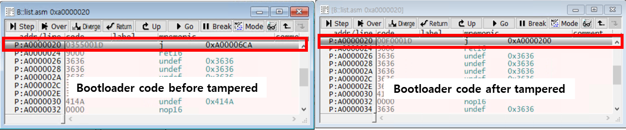
If you set a breakpoint at the start of the bootloader and modify the bootloader, the bootloader’s MAC will have already been calculated before jumping to the bootloader, so the modified bootloader code will be executed once.
However, after resetting the power, the MAC of the bootloader stored in the HSM is the MAC of the bootloader before the modification, and the newly calculated MAC of the modified bootloader is different. Therefore, the modified bootloader code will not be executed.
After a power reset, Trace32 cannot connect to the JTAG port, even with the correct password. This indicates that secure boot is functioning correctly and the CPU is prevented from transitioning from the SSW code to the modified bootloader.
My guess is that after the SSW code region verifies secure boot, it attempts to configure secure debug. However, it receives a secure boot fail response from the HSM and enters an infinite loop. As a result, the subsequent code is not executed, and secure debug is not configured, making JTAG connection impossible.
In this way, secure boot is a powerful security technique that completely blocks the execution of modified code from an attacker during the boot process. Once it is triggered, there is no way to recover the controller.